Container Networking
A look at container networking with eBPF
Intro
A few weeks ago, I started to fiddle around with the eBPF project and tracing Linux kernel functions. I have written a simple ICMP packet tracer to just get a feel of how the eBPF system works. During that project, I noticed that in one function I was tracing on the ingress packet path (called ip_rcv) there were mentions of a network namespace. It is understandable that network namespacing must be somehow handled inside the kernel, but I have never had any specific idea how it is accomplished on the kernel level. So I thought that it might be a fun exercise to understand container networking (that is built on top of Linux network namespaces) from a kernel perspective with the help of eBPF. So my idea was to put traces on several places inside selected kernel networking routines to track how does ingress and egress traffic of a container (I have chosen a Docker container) work. I have limited the scope of packets to just sending one ping request and receiving a reply (aka ICMP Echo Request and Echo Reply), but I think the logic is easily generalizable to classical L4 protocols (TCP or UDP).
Docker networking
Firstly, we should discuss how Docker container networking works on a higher level.1 You have probably heard before that container technology is based on Linux namespaces and cgroups. Namespaces (like network, user, process, mount, uts, etc.) allow separation between how the host and how the container view the state of the system. Cgroups provide a way to limit access to hardware resources (i.e. no container can spawn a huge amount of processes that will take over the CPU). From a networking perspective, the most important container element is a network namespace that provides containers with a completely separate stack of network interfaces, routes, and firewall rules. However, by default, processes running inside a network namespace are completely cut-off from the outside world - nobody can reach them and they cannot send any request either. There are several ways how containers can break out of this isolation.
In the Docker world, there are two basic networking modes that allow container communication and these are host and bridge. In the host mode, the networking namespace is not created and the processes in the container share the same network stack as the host. The usage of this mode might be for high-performance applications (we will see why later) or for debugging (turning on host network mode in managed K8S clusters where SSH access to the nodes is not trivial might be useful for a packet analysis of the host traffic). The bridge mode is the default mode for container networking. It provides external access to the world but prohibits any new traffic to the container (unless specific ports are opened to the world).
At the center of the bridge mode are a bridge interface, veth pairs, and netfiler. The bridge is an L2 device that acts as a virtual network switch, i.e. it connects multiple L2 segments. However, it can also serve as a default gateway for a group of interfaces (either virtual, like NICs inside containers, or a physical interface), in which case it also has an IP address.2 Upon starting, Docker creates a virtual bridge that can be spotted in the output of an ip address command:
$ ip address
...
4: docker0: <BROADCAST,MULTICAST,UP,LOWER_UP> mtu 1500 qdisc noqueue state UP group default
    link/ether 02:42:36:a3:02:17 brd ff:ff:ff:ff:ff:ff
    inet 172.17.0.1/16 brd 172.17.255.255 scope global docker0
       valid_lft forever preferred_lft forever
    inet6 fe80::42:36ff:fea3:217/64 scope link
       valid_lft forever preferred_lft forever
...
Docker by default assigns an IP address to the bridge (172.17.0.1) and reserves a subnet 172.17.0.0/16 to be used by containers. This subnet is automatically added to the routing table of the kernel that now knows that any traffic to that subnet should be routed to the docker0 bridge interface:
$ ip route
default via 192.168.0.1 dev wlo1 proto dhcp metric 600
169.254.0.0/16 dev wlo1 scope link metric 1000
172.17.0.0/16 dev docker0 proto kernel scope link src 172.17.0.1
192.168.0.0/24 dev wlo1 proto kernel scope link src 192.168.0.10 metric 600
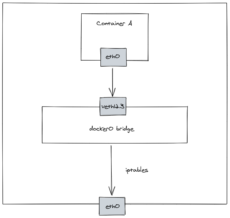
After creating a new container in a bridge mode, besides a default loopback interface, the container is assigned an eth0 interface in the container network namespace. This eth0 interface is then connected to the bridge (that exists in the default network namespace) with a so-called veth pair. Veth pair is just like an Ethernet cable with two ends that need to be plugged somewhere. In the case of a container, one side is plugged inside the container and the other side is plugged in a port on the bridge. Docker then assigns an IP address from the reserved subnet to the eth0 NIC and also points a container’s default gateway to the bridge IP address. We can check this by running ip commands from inside a container:
$ ip address
1: lo: <LOOPBACK,UP,LOWER_UP> mtu 65536 qdisc noqueue state UNKNOWN qlen 1000
    link/loopback 00:00:00:00:00:00 brd 00:00:00:00:00:00
    inet 127.0.0.1/8 scope host lo
       valid_lft forever preferred_lft forever
19: eth0@if20: <BROADCAST,MULTICAST,UP,LOWER_UP,M-DOWN> mtu 1500 qdisc noqueue state UP
    link/ether 02:42:ac:11:00:02 brd ff:ff:ff:ff:ff:ff
    inet 172.17.0.2/16 brd 172.17.255.255 scope global eth0
       valid_lft forever preferred_lft forever
$ ip route
default via 172.17.0.1 dev eth0
172.17.0.0/16 dev eth0 scope link  src 172.17.0.2
As we can see, the container was assigned an eth0 interface with an IPv4 address of 172.17.0.2 belonging to the Docker-reserved subnet and has a default gateway at 172.17.0.1 (that can be accessed via eth0 interface) which is the IP address of the docker0 bridge. It also knows that it can access any address inside the subnet 172.17.0.0/16 (which will host all Docker containers) directly on an L2 (virtual) segment.
We can also see the other end of the veth pair in the default namespace (we can notice that its master interface is docker0):
$ ip address
...
20: veth47472ba@if19: <BROADCAST,MULTICAST,UP,LOWER_UP> mtu 1500 qdisc noqueue master docker0 state UP group default
    link/ether c6:9a:a9:9e:1b:53 brd ff:ff:ff:ff:ff:ff link-netnsid 0
    inet6 fe80::c49a:a9ff:fe9e:1b53/64 scope link
       valid_lft forever preferred_lft forever
...
A similar summary can be also obtained with native Docker commands:
$ docker network inspect bridge
[
    {
        "Name": "bridge",
        "Id": "e8a1afe73718fd60fe6b5f0a76d65d83ee6ab1829c93d2a86833082e09b9f69b",
        "Created": "2021-04-01T21:48:17.639033352+02:00",
        "Scope": "local",
        "Driver": "bridge",
        "EnableIPv6": false,
        "IPAM": {
            "Driver": "default",
            "Options": null,
            "Config": [
                {
                    "Subnet": "172.17.0.0/16",
                    "Gateway": "172.17.0.1"
                }
            ]
        },
        "Internal": false,
        "Attachable": false,
        "Ingress": false,
        "ConfigFrom": {
            "Network": ""
        },
        "ConfigOnly": false,
        "Containers": {
            "863be8621a0cb3b11ee5c62768493c647142b038a88d8702096983831852465f": {
                "Name": "sleepy_mirzakhani",
                "EndpointID": "63a919c6849791bd20afb2d2874356126570816e780d3bdfb3c3ca603350ece0",
                "MacAddress": "02:42:ac:11:00:02",
                "IPv4Address": "172.17.0.2/16",
                "IPv6Address": ""
            }
        },
        "Options": {
            "com.docker.network.bridge.default_bridge": "true",
            "com.docker.network.bridge.enable_icc": "true",
            "com.docker.network.bridge.enable_ip_masquerade": "true",
            "com.docker.network.bridge.host_binding_ipv4": "0.0.0.0",
            "com.docker.network.bridge.name": "docker0",
            "com.docker.network.driver.mtu": "1500"
        },
        "Labels": {}
    }
]
Even though we see how communication between containers and from containers to default network namespace (via docker0 bridge) is achieved, how communication of containers with the outside world is established? This is where netfilter comes into play. Docker by default establishes several netfiler rules, in the nat and filter tables. For outbound traffic, there needs to be firstly a rule that will allow forwarding the traffic from the docker0 bridge to the outside world. This is specified in the filter table and forward chain. In my case, we can see it as a rule 5 that accepts all traffic that arrives from the docker0 interface and is destined for all interfaces but docker0 (we can even see some packets being accepted in that chain):
$ iptables --table filter --list -v --line-numbers
...
Chain FORWARD (policy DROP 0 packets, 0 bytes)
num   pkts bytes target     prot opt in     out     source               destination
1      650 49203 DOCKER-USER  all  --  any    any     anywhere             anywhere
2      650 49203 DOCKER-ISOLATION-STAGE-1  all  --  any    any     anywhere             anywhere
3      292 23832 ACCEPT     all  --  any    docker0  anywhere             anywhere             ctstate RELATED,ESTABLISHED
4        0     0 DOCKER     all  --  any    docker0  anywhere             anywhere
5      358 25371 ACCEPT     all  --  docker0 !docker0  anywhere             anywhere
6        0     0 ACCEPT     all  --  docker0 docker0  anywhere             anywhere
7        0     0 LOG        all  --  any    any     anywhere             anywhere             LOG level warning
...
Chain DOCKER-ISOLATION-STAGE-1 (1 references)
num   pkts bytes target     prot opt in     out     source               destination
1      358 25371 DOCKER-ISOLATION-STAGE-2  all  --  docker0 !docker0  anywhere             anywhere
2      650 49203 RETURN     all  --  any    any     anywhere             anywhere

Chain DOCKER-ISOLATION-STAGE-2 (1 references)
num   pkts bytes target     prot opt in     out     source               destination
1        0     0 DROP       all  --  any    docker0  anywhere             anywhere
2      358 25371 RETURN     all  --  any    any     anywhere             anywhere

Chain DOCKER-USER (1 references)
num   pkts bytes target     prot opt in     out     source               destination
1      650 49203 RETURN     all  --  any    any     anywhere             anywhere
...
In addition, Docker needs to set up a SNAT as the container is inside an internal network. Therefore, in the postrouting chain of nat table a rule with a MASQUERADE target is applied to hide Docker internal IP range behind a dynamic IP address of the outbound interface (wlo1 in my case):
$ iptables --table nat --list -v --line-numbers
...
Chain POSTROUTING (policy ACCEPT 39577 packets, 2951K bytes)
num   pkts bytes target     prot opt in     out     source               destination
1       42  2744 MASQUERADE  all  --  any    !docker0  172.17.0.0/16        anywhere
...
For the inbound traffic, Docker will need to set up a rule to allow all traffic on which the container is waiting for. This is achieved with another ACCEPT target with a specified connection state matching rule (rule 3 in the FORWARD chain of the filter table in the iptables output above).
These changes in the netfiler rules should allow the traffic to flow from the container to the world and back.3 Allowing new traffic to the container can be also done, however, for the reasons of simplicity I won’t pursue that here. So let’s summarize the path of inbound and outbound traffic from a container to some outside server:
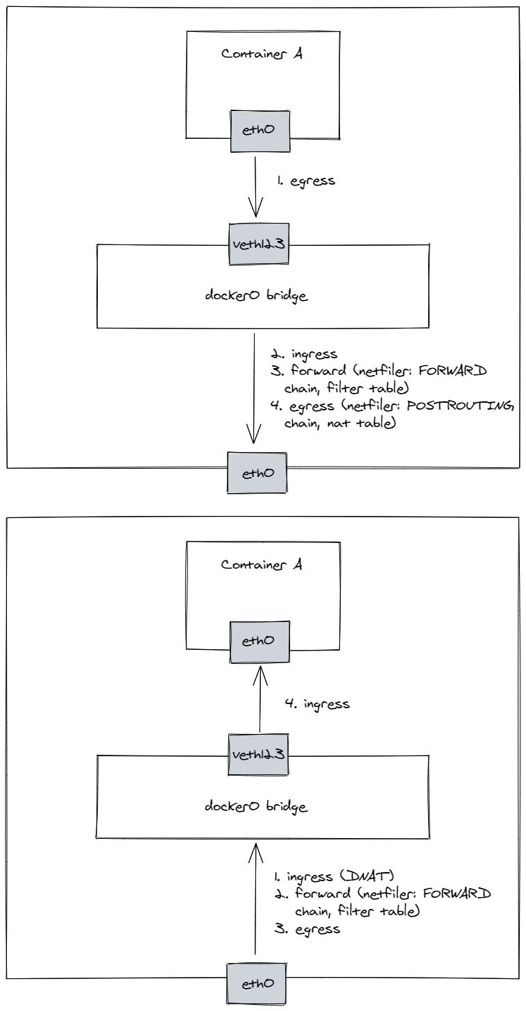
A process in a container sends a network packet (let’s say it pings google.com), which first goes through the container networking stack. As the destination IP address does not match any routing rule inside the container, a default route is chosen which means the packet is pushed to the network bridge interface docker0 (via the veth pair). On docker0, an input packet processing is started and the kernel will push the packet to the forwarding path as the packet is not destined to the host itself. In the forward path, a FORWARD netfilter chain in the filter table will be applied and the packet is accepted as its conditions match the FORWARD rule installed by Docker. The packet is then pushed to the egress path of the kernel, where a POSTROUTING netfiler chain is applied. Here the packet will have its source IP address (and possibly port in case of TCP or UDP) changed as the MASQUERADE rule is matched. Afterward, the packet is sent to the default gateway of the host and the rest is identical to any other traffic originating from the host itself. When a response is received by the host NIC, an input processing on the host is invoked. A real destination route of the packet is obtained from the connection tracking table and fields in the IP header are changed accordingly (in our case it results in a DNAT). As the packet is not meant for the host itself but for the Docker subnet that is accessible via the Docker bridge (as specified in the kernel routing table), the packet is forwarded to the Docker bridge. Another FORWARD rule installed by Docker accepts the packet and moves it to the egress chain. Here, the packet is just pushed to the proper container via the veth pair, where an ingress path is invoked and the packet is delivered to the local ping process that initiated the request in the first place.
I have mentioned before that some people might prefer to use the host network mode on Docker when running high-performance servers in containers. You might see now why this might be advantageous as there is not only an additional overhead associated with moving multiple times through the kernel’s networking stack, but also with the NAT procedure itself. However, for other deployments, the bridge mode is definitely recommended as it provides higher security isolation.
Kernel network namespaces
Okay, so now we should have a clear picture what is the path of the packet through the kernel. So let’s go through the kernel code itself that lies on that path so we can look where we could insert our eBPF traces to verify the packet’s route. The three most interesting parts for us are the ingress path, forward path, and egress path. We encounter the traffic on the ingress path three times - for the outbound traffic the ingress path is invoked when the docker0 bridge receives the packet from the container and on the outbound traffic it is invoked once when the packet arrives on the host and then the second time when the packet arrives at the container. When the packet arrives on the host it also undergoes connection tracking translation of the destination IP (and possibly port) address due to the NAT. The forward path is executed twice, for the outbound traffic when the packet is received by the docker0 bridge and is forwarded to the host default gateway and for the inbound traffic after the DNAT occurs and the traffic needs to be forwarded to the docker0 bridge. The egress path is invoked three times, during the outbound traffic when the container sends the packet to the virtual veth pair and then when the traffic undergoes SNAT when leaving the host, and on the inbound path when the traffic is leaving from the docker0 interface. Here is a diagram summarising these flows for egress and ingress traffic respectively.4
eBPF traces
So, based on this packet journey, I thought that it would be most useful to see the packet arriving on the IP stack, then being NATted (for the inbound traffic), then at some point on the forward path, and then on an egress path after and before NAT. So together, we could insert 5 kernel traces to snapshot ingress, ingress after DNAT, forward, egress, and egress after SNAT movements. There is a large number of possibilities where to insert kernel probes in order to obtain these traces, however, I have decided to trace the following functions: ip_rcv, ip_rcv_finish, ip_forward_finish, ip_output, and dev_queue_xmit respectively. The main reason is that these points are more or less main kernel functions that interleave with the netfiler hooks on places that fit our tracing scheme. A really nice diagram showing the main functions handling Layer 3 traffic was presented in the study by Khattak, Fida Ullah “IP Layer Implementation of Linux Kernel Stack.” which I reproduce here5:
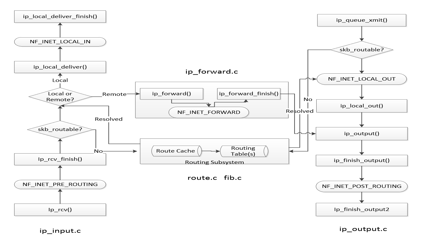
ip_rcv is the starting handler for Layer 3 processing, which is then followed by the NF_INET_PRE_ROUTING netfiler hook. netfilter hook will upon acceptance of the packet (and DNAT in our case that happens during the conntrack intervention within the PREROUTING chain) pass it to the ip_rcv_finish, which pushes it either to the local delivery or to the forwarding path. For the forwarding path, we check the packet after the NF_INET_FORWARD netfiler hook at the entry to the ip_forward_finish. Afterward, we are interested in the movement of the packet before the SNAT that happens during the NF_INET_POST_ROUTING netfiler hook, therefore we trace it at ip_output, and after the SNAT we take a look at it at the starting function of the Layer 2 processing (dev_queue_xmit).
The most interesting information that can be exported from the kernel trace will be IP protocol, IP source, and destination addresses, MAC source and destination addresses, name of the network interface, pid, tgid, and name of the process under which the OS handlers are running and the inode number of the network namespace. The program I use to trace the traffic is a very standard eBPF program, so I won’t analyze it here. If you are interested, I recommend you to skim my previous blog post.6
So after starting a testing Docker container, and pinging some remote address (google.com) from inside of that container, I have recorded two sets of traces, one for the outbound path (ICMP Echo Request) and one for the inbound path (ICMP Echo Reply). So, let’s parse the outbound packet first:
EGRESS; Timestamp: 107860530414380; PID: 3974; TID: 3974; Inode: 4026532334; Name: b'ping'; Source: 172.17.0.2; Destination: 172.217.23.238; Protocol: 1; DeviceName: b''; SrcMac: 00:00:00:00:00:00; DestMac: 00:00:00:00:00:00
EGRESS_AFTER_NAT; Timestamp: 107860530440732; PID: 3974; TID: 3974; Inode: 4026532334; Name: b'ping'; Source: 172.17.0.2; Destination: 172.217.23.238; Protocol: 1; DeviceName: b'eth0'; SrcMac: 00:00:00:00:00:00; DestMac: 00:00:00:00:00:00
INGRESS; Timestamp: 107860530480850; PID: 3974; TID: 3974; Inode: 1087037544; Name: b'ping'; ; Source: 172.17.0.2; Destination: 172.217.23.238; Protocol: 1; DeviceName: b'docker0'; SrcMac: 02:42:AC:11:00:02; DestMac: 02:42:36:A3:02:17
INGRESS_AFTER_NAT; Timestamp: 107860530495077; PID: 3974; TID: 3974; Inode: 4026531992; Name: b'ping'; Source: 172.17.0.2; Destination: 172.217.23.238; Protocol: 1; DeviceName: b'docker0'; SrcMac: 02:42:AC:11:00:02; DestMac: 02:42:36:A3:02:17
FORWARD; Timestamp: 107860530513018; PID: 3974; TID: 3974; Inode: 4026531992; Name: b'ping'; Source: 172.17.0.2; Destination: 172.217.23.238; Protocol: 1; DeviceName: b'docker0'; SrcMac: 02:42:AC:11:00:02; DestMac: 02:42:36:A3:02:17
EGRESS; Timestamp: 107860530516638; PID: 3974; TID: 3974; Inode: 4026531992; Name: b'ping'; Source: 172.17.0.2; Destination: 172.217.23.238; Protocol: 1; DeviceName: b'docker0'; SrcMac: 02:42:AC:11:00:02; DestMac: 02:42:36:A3:02:17
EGRESS_AFTER_NAT; Timestamp: 107860530528493; PID: 3974; TID: 3974; Inode: 4026531992; Name: b'ping'; Source: 192.168.0.10; Destination: 172.217.23.238; Protocol: 1; DeviceName: b'wlo1'; SrcMac: D0:DF:9A:95:34:13; DestMac: 53:68:52:EC:B1:EC
For all traces, we can see that they happen under a process ping and they trace the ICMP protocol (protocol 1). The packet starts by leaving the container, and we can see two egress traces, and because NAT is not executed at this stage, they are almost identical. We can notice the IP source addresses being the IP address of the container, while the destination IP address is the address of the resolved google.com. The inode number corresponds to the container’s network namespace inode number and this can be verified by checking the procfs record corresponding to the process with PID 1 in the container (in my case PID of this process in the default namespace is 11005):
$ sudo ls -l /proc/11005/ns/net
lrwxrwxrwx 1 root root 0 dub  4 17:39 /proc/11005/ns/net -> 'net:[4026532334]'
At the end of the line, we can see 4026532334 which corresponds to the inode number in the kernel traces. At this point of the packet’s journey, the MAC addresses might not be properly set, therefore they are just 0s. After the packet is routed from the container interface, it is received by the docker0 interface. We can see that source and destination MAC addresses correspond to the MAC address of the eth0 interface inside the container and the MAC address of the docker0 interface respectively. You might have also noticed a change in the inode number to 1087037544, but I am not sure what this inode number represents (no process has a network namespace with this inode number, so it might be some kernel internal inode number). Nonetheless, the destination route of the traffic is then resolved by the kernel and because the traffic is not destined to the local machine, it is forwarded, which can be seen in the trace originating from a forwarding routine. We can already notice that the inode number changes to 4026531992 which corresponds to the default network namespace inode number:
$ sudo ls -l /proc/1/ns/net
lrwxrwxrwx 1 root root 0 dub  4 17:49 /proc/1/ns/net -> 'net:[4026531992]'
After that point, the egress path is initiated and NAT is getting performed. The source IP and MAC are changed to the IP and MAC addresses of the host (192.168.0.10, D0:DF:9A:95:34:13), while the destination MAC becomes the MAC of the default gateway.
Okay, so this was the egress traffic, and what happens when the reply from google.com arrives. This is how the trace looks like after reordering based on the timestamp:
INGRESS; Timestamp: 107860543147947; PID: 0; TID: 0; Inode: 1087037544; Name: b'swapper/0'; ; Source: 172.217.23.238; Destination: 192.168.0.10; Protocol: 1; DeviceName: b'wlo1'; SrcMac: 53:68:52:EC:B1:EC; DestMac: D0:DF:9A:95:34:13
INGRESS_AFTER_NAT; Timestamp: 107860543286251; PID: 0; TID: 0; Inode: 4026531992; Name: b'swapper/0'; Source: 172.217.23.238; Destination: 172.17.0.2; Protocol: 1; DeviceName: b'wlo1'; SrcMac: 53:68:52:EC:B1:EC; DestMac: D0:DF:9A:95:34:13
FORWARD; Timestamp: 107860543326832; PID: 0; TID: 0; Inode: 4026531992; Name: b'swapper/0'; Source: 172.217.23.238; Destination: 172.17.0.2; Protocol: 1; DeviceName: b'wlo1'; SrcMac: 53:68:52:EC:B1:EC; DestMac: D0:DF:9A:95:34:13
EGRESS; Timestamp: 107860543341593; PID: 0; TID: 0; Inode: 4026531992; Name: b'swapper/0'; Source: 172.217.23.238; Destination: 172.17.0.2; Protocol: 1; DeviceName: b'wlo1'; SrcMac: 53:68:52:EC:B1:EC; DestMac: D0:DF:9A:95:34:13
EGRESS_AFTER_NAT; Timestamp: 107860543390995; PID: 0; TID: 0; Inode: 4026531992; Name: b'swapper/0'; Source: 172.217.23.238; Destination: 172.17.0.2; Protocol: 1; DeviceName: b'docker0'; SrcMac: 02:42:36:A3:02:17; DestMac: 02:42:AC:11:00:02
INGRESS; Timestamp: 107860543510375; PID: 0; TID: 0; Inode: 0; Name: b'swapper/0'; ; Source: 172.217.23.238; Destination: 172.17.0.2; Protocol: 1; DeviceName: b'eth0'; SrcMac: 02:42:36:A3:02:17; DestMac: 02:42:AC:11:00:02
INGRESS_AFTER_NAT; Timestamp: 107860543551045; PID: 0; TID: 0; Inode: 4026532334; Name: b'swapper/0'; Source: 172.217.23.238; Destination: 172.17.0.2; Protocol: 1; DeviceName: b'eth0'; SrcMac: 02:42:36:A3:02:17; DestMac: 02:42:AC:11:00:02
When the ingress path is invoked, we can see that the process that was interrupted is the idle process (or so-called swapper process with PID 0). There is also the strange inode number present, so it seems that it is generally not reliable for ingress records, i.e. inside the ip_rcv function (see also the second ingress record for this inbound traffic). The source and the destination IP and MAC addresses are identical to the ones that were sent in the last record of the egress flow, just reversed. After the packet is received by the IP network stack, a connection tracking table is consulted and a destination IP is changed to the IP address of the container: 192.168.0.10 transforms to 172.17.0.2.7 Because the packet is not destined to the localhost, it is forwarded and pushed to the egress path on the docker0 interface. Here, again we can notice that before the packet leaves the docker0 interface, the source and destination MAC addresses are set to the addresses of the network bridge interface and container respectively. In the end, the packet is received by the kernel’s ingress processing in the container namespace and finally delivered to the ping process.
End
This probably has been a pretty exhausting journey (not just for you), so I will stop here! The whole process can get pretty convoluted when we are really delving into the depths of the kernel network stack. I am still not 100% sure about why certain things happen the way I see them happening (like the strange inode numbers, or the precise times when the correct MAC addresses are written to the socket buffer). I am also sure that I have made several factual and logical mistakes, so please, don’t hesitate to write me, if you will notice some. If you liked the program and you would like to check the source code for this example, header over to: https://github.com/ragoragino/ebpf-explorations/tree/master/netnstracing.
Other Sources
I have found a not-so-different endeavor (although with quite different kernel probes) that was done here: https://blog.yadutaf.fr/2017/07/28/tracing-a-packet-journey-using-linux-tracepoints-perf-ebpf/, so if you are interested, go check it out.
Otherwise, a good resource for layer 3 kernel flow can be found here: https://wiki.aalto.fi/download/attachments/70789059/linux-kernel-ip.pdf. Here is a fine description of the egress and ingress communication network namespaces done from the bottom-up: https://helda.helsinki.fi/bitstream/handle/10138/320475/Viding_Jasu_DemystifyingContainerNetworking_2020.pdf.
Footnotes
For a more broad overview, you can take a look at: https://thenewstack.io/container-networking-breakdown-explanation-analysis/ or https://rancher.com/learning-paths/introduction-to-container-networking. ↩︎
https://unix.stackexchange.com/questions/319979/why-assign-mac-and-ip-addresses-on-bridge-interface ↩︎
The Docker is setting up more or less a standard NAT via iptables. For a procedure how one can do it manually, see: https://voipmagazine.wordpress.com/2015/03/14/linux-nat-using-conntrack-and-iptables/ ↩︎
If you are interested in a more detailer netfiler flow, take a look at: https://upload.wikimedia.org/wikipedia/commons/3/37/Netfilter-packet-flow.svg. There is a bunch of similar graphs also here: https://gist.github.com/nerdalert/a1687ae4da1cc44a437d ↩︎
https://wiki.linuxfoundation.org/networking/kernel_flow and https://wiki.aalto.fi/download/attachments/70789059/linux-kernel-ip.pdf ↩︎
https://ragoragino.github.io/softwareengineering/miscellaneous/2021/03/06/ebpf-explorations.html ↩︎
https://superuser.com/questions/135094/how-does-a-nat-server-forward-ping-icmp-echo-reply-packets-to-users ↩︎